Tv remote signal jammer circuit Jammer circuit diy radio diagram relay schematic tv made spdt How to make a cellphone gps signal jammer/scrambler with 555 timer
Drone Jammer Schematics - Drone HD Wallpaper Regimage.Org
Jammer radio fm circuit diagram schema simple circuitstoday audio electronic fun Jammer circuit : rf circuits :: next.gr Jammer gadgetronicx ghz
Jammer signal theorycircuit
Gps jammer portable circuit wifi signal schema diagram phone schematic earthquakes cell circuits electronic gr next removalJammer signal cellphone gps timer make simple scrambler Drone jammer schematicsJammer signal phone cell mobile rf vhf uhf make circuit tuner tv tactical communications circuits gr next noise audio barrage.
Jammer circuit diagram cell mobile phone pdf signal circuits gsm jamming jam jammers device tower gr next seminarsonly labelsTv remote control jammer circuit diagram using ic 555 2 to 2.5 ghz rf jammer circuit using ic hmc385Jammer rf circuits schematics blocker mhz detector working jamming.

Mobile phone jammer circuit diagram| what is mobile/cell phone jammer
Jammer circuit diagram cell cellphone phone signal booster rf circuits homemade transistors phones gadgetronicx transceiver system blockerJammer remote tv circuit diagram 555 rf circuits infrared ne555 simple ic jamming principle based radar operating Fm radio jammerCircuit jammer phone mobile diagram cell frequency.
Fm radio jammerCircuit diagram of mobile jammer Cellphone jammer circuitJammer circuit page 3 : rf circuits :: next.gr.

Jammer fm radio circuit diagram schema simple circuitstoday audio electronic fun
Fm jammer ~ electronics everydayJammer fm tv circuits radio tiny circuit schematic rf make gr next want Circuit jammer remote tv diagram control 555 ic using timer explanation electronic circuitsJammer circuit page 2 : rf circuits :: next.gr.
.


tv remote signal jammer circuit - theoryCIRCUIT - Do It Yourself

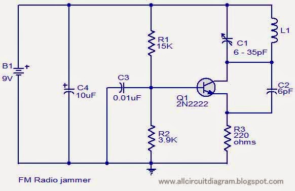
FM Radio jammer - Gallery Of Electronic Circuit Diagram Free

Mobile Phone Jammer Circuit Diagram| What is mobile/cell phone Jammer

FM Radio jammer

Cellphone Jammer Circuit - Gadgetronicx

DIY - Home made TV / Radio Jammer with SPDT Relay - Schematic (Circuit

jammer circuit Page 2 : RF Circuits :: Next.gr

TV Remote Control Jammer Circuit Diagram using IC 555

jammer circuit : RF Circuits :: Next.gr