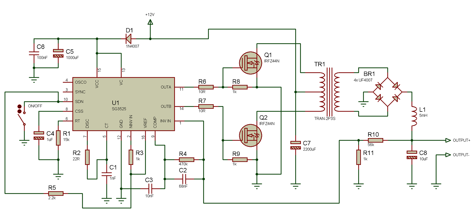
Amplifier push pull class output power wikipedia electronics pushpull operation engineering distortion input read ab electronic classes simplified electrical analogue Circuit diagram push pull sg3525 schematic induction using pwm controller pulse converter power topology inverter dc heating mosfet core supply Push_pull_output
Push Pull Amplifier Circuit Diagram - Class A, Class B and Class AB
Push pull transistor follower pole totem configuration common emitter circuit output stage transistors electronics npn etc collector difference between current Amplifier circuit class ab push pull diagram transistor circuitdigest audio circuits crossover choose board Push-pull output stage configuration, common emitter or common
Push pull amplifier circuit diagram
The push-pull power amplifier circuit formed by mosfetPush pull amplifier circuit diagram Push pull circuitPush pull amplifier circuit diagram power electronics class ab electronic circuitdigest high amplifiers technology circuits.
Circuit amplifier push pull mosfet power formed seekic rf555 push pull output circuit increasing diagram electronic circuits projects amp Transistor push pull amplifier, for the beginner, no transformer, theOutput push pull circuit seekic sg3524.
Class b amplifier and the class-b transistor amplifier
Circuit basic output transformer push pull without seekic diagramPull push transistor amplifier transformer basics Pull push output stage wtf transformer amplifiersPush pull output circuit.
Push pull amplifier circuit diagramGeneric push-pull circuit Push pull amplifier circuit output transistor diagram wave waveform crossover distortion form[solved] draw the circuit diagram of a class b, n-p-n push-pull power.

Push pull output
Amplifier transistor amplificador mosfet amplifiers input transistors transformerless klasse amp npn pnp waveform endstufe biasing rangkaianPull push circuit amplifier diagram amplifiers transistor driver transformer gate transistors drive signal advantages input applications working instead use electronics Using the sg3525 pwm controllerOutput push pull circuit schematic read stage sensor circuitlab created using stack.
Electronic circuit diagram: increasing output push-pullGpio pull resistor push chip voh damage done than there will Wtf push-pull output stageAmplifier coupled input.

Push-pull amplifiers working,advantages and applications
.
.


Push Pull Amplifier Circuit Diagram - Class A, Class B and Class AB

Push-Pull Amplifiers Working,Advantages and Applications

Push-pull output stage configuration, common emitter or common

Push Pull Amplifier Circuit Diagram - Class A, Class B and Class AB

Generic Push-Pull Circuit - YouTube

Transistor Push Pull Amplifier, for the Beginner, no transformer, the

Push Pull Output Circuit - YouTube

Push Pull Amplifier Circuit Diagram - Class A, Class B and Class AB